Windows Me installation Process

3:16 AM Posted In Edit This 1 Comment »


  1. A Windows ME CD


2. A Computer


  1. Your Chosen CD-Rom Boot Media (CD-Rom Support)


  2. Your Chosen Method (Different Ways)


Windows ME Install will firstly run Scandisk after you have started the install, let this complete, if you exit windows will not allow you to complete the install of Windows ME.


This is the Screen you will be met with after scandisk completes. You are now ready to begin the installation.


The following screen is where you will install windows into, C:\Windows is the default, you can change this if needed. Click next to continue.


Now watch as windows prepares to start.


The following window will appear. For most Desktop users select Typical install (Default) for laptop users select Portable. The other two options speak for themselves. Click next to continue.


Just leave the next section as is. It can be modified later in Add/Remove programs which is located in the control panel. Click next to continue.


Now Select the country you are located in. Click next to continue.


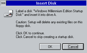
You will now be prompted to make a startup disk. You can press cancel at this point which will take you to the next screen or create the disk.


Whether you made the disk or not the following screen will appear. Click OK to continue.


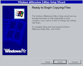
The system is now ready to begin copying files. Click on finish.

Windows will begin copying files. You have to time for a cup of tea, a cigarette or even a long cold drink of beer.

The next screen will eventually appear, but if you are not even near the computer it will restart itself in 15 secs

You will then be faced with a Dos screen saying something like what is below. Just be patient and open another cold one.

You should be opening your 2nd can of beer at this moment. Your computer is working Hard with the Hardware Setup.

At Last something for you to do. Type in a name and a Company name (optional) then click next.

You will not be faced with Microsoft's License Agreement. Read through then agree or disagree to it by clicking on appropriate area. Then Click next to continue.

Now you need to enter your product key. This will either be with your CD or the Windows ME book that's supplied with your computer. Once entered correctly click next to continue.

If you entered the product Key correctly then the next screen will appear.

The next screen will appear next, but if your not even near the computer it will restart itself in 15 seconds.

System will now update shortcuts.

And other Windows components. Your system will then need to restart again.

Once restarted you will be asked for a user name and password. Enter as needed.

System will update a few more files and you will be finally at the desktop. Windows install complete. All you need to do now is install the drivers for any hard ware that Windows ME has not picked up.


Installation Process

1:44 AM Posted In Edit This 0 Comments »
Windows XP Installation


1.Ensure that your computer meets or exceeds the minimum system requirements to run Windows XP:

◦300 Mhz Intel or AMD CPU
◦128 Megabytes of system RAM (It can work with 64 Megabytes of RAM but its not recommended)
◦1.5 Gigabytes of available drive space
◦Super VGA 800x600 Display Adapter
◦CD or DVD-ROM
◦Keyboard and mouse, or other pointing devices
◦Network Interface Adapter required for Internet and Network Connectivity


2.Ensure you have a Windows XP Product Key. It is printed on a sticker on your software package. It is a string of 5 groups of characters (each 5 long), separated by dashes, resulting in 25 characters in all.
It looks like this: HHHCF-WCF9P-M3YCC-RXDXH-FC3C6.
When the software has almost finished installing, you will be asked for it.You need the product key to complete installing Windows.


3.Before inserting the CD, you'll have to enter bios (in most cases by presing DEL on system startup) and select your primary boot device CDrom. Insert the Windows XP Installation Disc and start your computer. When prompted to "Press any key to boot from CD," press a key on the keyboard.
4.The installation program will check your hardware, install default-set drivers, and load files necessary for installation. When arriving at the "Welcome to Setup" screen, Press ENTER to begin the installation process.


5.Read the License Agreement, and press F8 indicating you agree to its terms.
6.On the next screen, you are presented with a summary of the available partitions on your installed hard drives. At this point, you should see only one entry, "Unpartitioned Space." It will be highlighted in grey. Press C on your keyboard to begin creating partitions for the drive.
7.Enter the size in megabytes for the new partition. If you intend to install only one drive, enter the maximum amount shown. If you wish to create multiple partitions on a single drive, remember that Windows XP requires at least 1.5 Gigabytes of space, plus swap space, and areas for temporary files. A good rule of thumb is not to install Windows XP on a partition less than 5 Gigabytes, unless you wish to impact performance. When calculating, remember that there are 1,024 Megabytes per Gigabyte. Press ENTER once you have chosen your desired partition size.


8.The system will create your new partition, and you will now be at the partition summary screen once again. Select your new partition, usually labeled "C: Partition 1 [Raw]" and press ENTER.


9.Select either "Format the Partition using the NTFS File System" OR "Format the Partition using the FAT File System," and press ENTER. NTFS is the preferred method, supporting a larger amount of disk space per partition than FAT, and including security features at the file system level. NTFS also includes system level compression. If your partition is larger than 32 Gigabytes, you must choose NTFS. However, with a partition less than 32 Gigabytes, you can choose FAT, and convert to NTFS later should you desire. Be aware that NTFS cannot be converted back to FAT.
It is highly recommended to avoid Quick Format, as this skips an important process that checks the hard drive for errors or bad sectors. This scan is what consumes the majority of the time taken when performing a full format. If there are errors on a disk at the physical level, it's best to catch them now rather than later.


10.The system will now format the partition. The length of time this process requires depends on the speed and size of the drive, and the type of file system you selected earlier. In most cases, the larger the partition, the longer the process will take.


11.Windows will now start copying files from the installation disc and prompt you to reboot the computer when the process is completed. Press ENTER when prompted to reboot, otherwise it will do so automatically after 15 seconds.


12.This is the most time consuming part. When the computer reboots, do not press enter to boot from the disc this time, rather allow the computer to boot from the hard drive. If you are greeted with the Windows XP Boot screen, all is well so far.


13.Now the setup program will display various marketing information to you as it installs and configures itself to your system. The estimated time remaining is displayed in the lower left corner.
Note: it is normal for the screen to flicker, turn on and off, or resize during this process.


14.Sooner or later, a dialog window will appear, asking you to choose your Regional settings. Select appropriate settings native to your area. Click the "Next" button when that is completed.


15.Enter your Product Key, (otherwise known as a CD or Install Key,) at this window. You will not be able to complete this process without a valid Key. Click "Next" to continue.
16.If your computer is going to be on a LAN (Local Area Network) at home, or even just for kicks, give it a name.


17.Select your time zone, and ensure that the date/time are correct. Click "Next" to continue.


18.Leave "Typical Settings" selected for Network Setup, unless you have a specialized access device or protocol required. Refer to the documentation for that device for installation procedures.
19.Setup will continue to install other devices and peripherals connected to your machine, give you marketing and capability information, then reboot as before.


20.Congratulations! You've installed Windows XP. There are a few more additional set-up routines required, but you have completed the installation. Remove the CD from the drive.


21.Upon Reboot, click Yes when you are informed Windows will be changing your visual settings to improve quality.


22.In the next box, if you can read the text, press the "OK" button.


23.A similar screen to Part 2 of the install process will appear. If your computer is connected to the internet, select your connection type. Press Next to continue.


24.If connected to the Internet, Select "Activate Now."
25.After the Activation Process, a window will appear allowing you to select the users for the computer. Enter your name, and the names of others who will be using the machine. Press Next to continue.


26.You will now be looking at the default Windows XP Desktop.

1:59 AM Posted In Edit This 5 Comments »


RESOURCE ALLOCATION GRAPH


Resource Allocation Graph
• Deadlock can be described through a resource allocation
graph.
• The RAG consists of a set of vertices P={P1,P2 ,…,P n} of
processes and R={R1,R2,…,Rm} of resources.
• A directed edge from a processes to a resource, Pi->R j, implies
that Pi has requested Rj.
• A directed edge from a resource to a process, Rj->Pi, implies
that Rj has been allocated by Pi.
• If the graph has no cycles, deadlock cannot exist. If the graph
has a cycle, deadlock may exist.


1.How would you know if theres a deadlock base on the resource
allocation graph?
=


Example of a Resource Allocation Graph


-REQUEST: if process Pi has no outstanding request, it can request simultaneously any number (up to multiplicity) of resources R1, R2, ..Rm. The request is represented by adding appropriate requests edges to the RAG of the current state.
-ACQUISITION: if process Pi has outstanding requests and they can all be simultaneously satisfied, then the request edges of these requests are replaced by assignment edges in the RAG of the current state
-RELEASE: if process Pi has no outstanding request then it can release any of the resources it is holding, and remove the corrisponding assignment edges from the RAG of the current state.


-Process
-Resource Type with 4 instances
-Pi requests instance of Rj
-Pi is holding an instance of Rj


Resource Allocation Graph With A Deadlock


• Deadlock Prevention & Avoidance: Ensurethat the system will never enter a deadlockstate
• Deadlock Detection & Recovery: Detect that adeadlock has occurred and recover
• Deadlock Ignorance: Pretend that deadlockswill never occur


Resource Allocation Graph With A Cycle But No Deadlock


Safe, Unsafe , Deadlock State


Basic Facts


-If graph contains no cycles Þ no deadlock.
-If graph contains a cycle Þ
-if only one instance per resource type, then deadlock.
-if several instances per resource type, possibility of deadlock.

Resource-Allocation Graph For Deadlock Avoidance


-Simplest and most useful model requires that each process declare the maximum number of resources of each type that it may need.
-The deadlock-avoidance algorithm dynamically examines the resource-allocation state to ensure that there can never be a circular-wait condition.
-Resource-allocation state is defined by the number of available and allocated resources, and the maximum demands of the processes.


Unsafe State In Resource-Allocation Graph


Traffic Deadlock for Exercise


Resource-Allocation Graph and Wait-for Graph


Deadlock Detection

3:54 AM Posted In Edit This 0 Comments »
„ Allow system to enter deadlock state

„ Detection algorithm

„ Recovery scheme

Deadlock Recovery

3:47 AM Posted In Edit This 1 Comment »
Recovery from Deadlock

• Recovery through preemption

– take a resource from some other process

– depends on nature of the resource

• Recovery through rollback

– checkpoint a process state periodically

– rollback a process to its checkpoint state if it is found deadlocked

• Recovery through killing processes

– kill one or more of the processes in the deadlock cycle

– the other processes get its resources

• In which order should we choose process to kill?

Deadlock Prevention

3:46 AM Posted In Edit This 0 Comments »
Attacking the Mutual Exclusion Condition:

• Some devices (such as printer) can be spooled

– only the printer daemon uses printer resource

– thus deadlock for printer eliminated

• Not all devices can be spooledRestrain the ways requests can be made to break one of the four necessary conditions for deadlocks.

Methods for Handling Deadlocks

3:45 AM Posted In Edit This 0 Comments »
• Ignore the problem and pretend that deadlocks would never occur

• Ensure that the system will never enter a deadlock state (prevention or avoidance)

• Allow the system to enter a deadlock state and then detect/recover

Deadlock Characterization

3:37 AM Posted In Edit This 2 Comments »

Deadlock CharacterizationDeadlock can arise if four conditions hold simultaneously:
Mutual exclusion: only one process at a time can use a resource
Hold and wait: a process holding at least one resource is waiting to acquire additional resources held by other processes
No preemption: a resource can be released only voluntarily by the process holding it, after that process has completed its task
Circular wait: there exists a set {P0, P1, …, Pn, P0} of waiting processes such that
– P0 is waiting for a resource that is held by P1,
– P1 is waiting for a resource that is held by P2,
– …,
– Pn–1 is waiting for a resource that is held by Pn,
– and Pn is waiting for a resource that is held by P0.

4:26 AM Posted In Edit This 0 Comments »
real-time scheduling

3:57 AM Posted In Edit This 0 Comments »
Thread Scheduling


An application can be implemented as a set of threads that cooperate and execute concurrently in the same address space. Criteria: When related threads run in parallel perf. improves.

Load sharing: pool of threads, pool of processors.

Gang scheduling: Bunch of related threads scheduled together.

Dedicated processor assignment: Each program gets as many processors as there are parallel threads.

Dynamic scheduling: More like demand scheduling.


CPU SCHEDULING ALGORITMS

11:16 PM Posted In Edit This 0 Comments »
Scheduling Algorithms

1.First-come, first-served (FCFS) scheduling
2.Shortest-job first (SJF) scheduling
3.Priority scheduling
4.Round-robin scheduling
5.Multilevel queue scheduling
6.Multilevel feedback queue scheduling

First-come, First-served(FCFS) scheduling
-is the simplest scheduling algorithm, but it can cause short processes to wait for very long processes.

Shortest-job-first (SJF) scheduling
-is provably optimal, providing the shortest average waiting time. Implementing SJF scheduling is difficult because predicting the length of the next CPU burst is difficult. The SJF algorithm is a special case of the general

Comments: SJF is proven optimal only when all jobs are available simultaneously.
Problem: SJF minimizes the average wait time because it services small processes before it services large ones. While it minimizes average wiat time, it may penalize processes with high service time requests. If the ready list is saturated, then processes with large service times tend to be left in the ready list while small processes receive service. In extreme case, where the system has little idle time, processes with large service times will never be served. This total starvation of large processes may be a serious liability of this algorithm.
Solution: Multi-Level Feedback Queques

Multi-Level Feedback Queue
Several queues arranged in some priority order.
Each queue could have a different scheduling discipline/ time quantum.
Lower quanta for higher priorities generally.
Defined by:

  • # of queues
  • scheduling algo for each queue
  • when to upgrade a priority
  • when to demote

SUBSTANTIAL INFORMATION ABOUT THREAD OF ATLEAST THREE OS Posted by ELIEZER

11:00 PM Posted In Edit This 0 Comments »

Windows Server 2008

Kernel improvements are significant because the kernel provides

  • low-level operating system functions,
  • including thread scheduling,
  • interrupt and exception dispatching,
  • multiprocessor synchronization, and
  • a set of routines and basic objects that the rest of the operating system uses to implement higher-level constructs.

WINDOWS XP THREAD

Implements the one-to-one mapping
Each thread contains
-> A thread id
-> Register set
-> Separate user and kernel stacks
-> Private data storage area
The register set, stacks, and private storage area are known as the context of the threads
The primary data structures of a thread include:
-> ETHREAD (executive thread block)
-> KTHREAD (kernel thread block)
-> TEB (thread environment block)

WINDOWS NT’s Threads


- Primary thread - When a process is created, one thread is generated along with it.

This object is then scheduled on a system wide basis by the kernel to execute on a processor.
After the primary thread has started, it can create other threads that share its address space and system resources but have independent contexts, which include execution stacks and thread specific data. A thread can execute any part of a process' code, including a part currently being executed by another thread.

It is through threads, provided in the Win32 application programmer interface (API), that Windows NT allows programmers to exploit the benefits of concurrency and parallelism.

- Fiber - is NT’s smallest user-level object of execution. It executes in the context of a thread and is unknown to the operating system kernel. A thread can consist of one or more fibers as determined by the application programmer. ˝Some literature ˝[1,11] assume that there is a one-to-one mapping of userlevel objects to kernel-level objects, this is inaccurate. Windows NT does ˝provide the means for many-to-many ˝scheduling. However, NT's design is poorly documented and the application programmer is responsible for the control of fibers such as allocating memory, scheduling them on threads and preemption.

Thread

3:11 AM Posted In Edit This 0 Comments »


  • Single-threaded process has one program counter specifying location of next instexecuteO Process executes instructions sequentially, one at a time, until completion
  • Multi-threaded process has one program counter per thread


Benifits of Multithreaded process


User Threads

*Thread management done by user-level threads library

*Three primary thread libraries:

*POSIX Pthreads
*Win32 threads
*Java thread


Kernel Threads

Supported by the Kernel

Examples

Windows XP/2000

Solaris

Linux

Tru64 UNIX

Mac OS


Thread library


The threads library allows concurrent programming in Objective Caml. It provides multiple threads of control (also called lightweight processes) that execute concurrently in the same memory space. Threads communicate by in-place modification of shared data structures, or by sending and receiving data on communication channels


-it is implemented by time-sharing on a single processor. It will not take advantage of multi-processor machines. Using this library will therefore never make programs run faster. However, many programs are easier to write when structured as several communicating processes.


Multithreading Models


The supports for threads can be provided either at the user level, called user threads, or by the kernel, called kernel threads, in which kernel threads are supported and managed directly by the OS. All contemporary OS support kernel threads. „ Ultimately, there must be a relationship between user threads and kernel threads, and there are three common ways of establishing relationships


*Many-to-One


many user threads are mapped into one kernel thread (Fig 4.2 in textbook on page 126, slide 3.45). Thread management is done by the thread library in use space, so this is very efficient; but the entire process will be blocked if one thread makes a blocking system call since only one thread can access the kernel at one time. Also multiple threads are unable to in parallel on multi-processors.


Many user-level threads mapped to single kernel thread

Examples:

Solaris Green Threads

GNU Portable Threads


*One-to-One


each user thread is mapped into one kernel thread. It provides maximum concurrency by allowing another thread to run when a thread (currently running) is blocked; It also allows multiple threads (within a process) to run in parallel on multiprocessors. The drawback is that the creation of a user thread requires the creation of the corresponding kernel thread. There is usually more overhead creating kernel thread than creating user thread, and most implementation of this model restricts the number of threads that can be supported by the system.

Each user-level thread maps to kernel thread

Examples

Windows NT/XP/2000

Linux

Solaris 9 and later


*Many-to-Many Model


this typically allows many user-level threads to be mapped to a smaller or equal number of kernel threads, which is a hybrid model of the first two models. It provides better concurrency than many-to-one model (less than one-to-one model), yet is flexible in that it can create many user-threads not restricted by the number of kernel threads

Allows many user level threads to be mapped to many kernel
threads

Allows the operating system to create a sufficient number of
kernel threads

Solaris prior to version 9

Windows NT/2000 with the
ThreadFiber package


Interprocess Communication

2:09 AM Posted In Edit This 0 Comments »
Interprocess Communication

Direct communication:The sender and receiver can communicate in either ofthe following forms:• synchronous—involved processes synchronize at everymessage. Both send and receive are blockingoperations. This form is also known as a rendezvous.• asynchronous—the send operation is almost alwaysnon-blocking. The receive operation, however, can haveblocking (waiting) or non-blocking (polling) variants. Processes must explicitly name the receiver or senderof a message (symmetric addressing).– send (P, message). Send message to process P.– receive (Q, message). Receive message from Q.In a client-server system, the server does not have toknow the name of a specific client in order to receivea message. In this case, a variant of the receiveoperation can be used (asymmetric addressing).– listen (ID, message). Receive a pending (posted)message from any process; when a message arrives,ID is set to the name of the sender. In this form of communication the interconnectionbetween the sender and receiver has the followingcharacteristics:• A link is established automatically, but the processesneed to know each other’s identity.• A unique link is associated with the two processes.• Each pair of processes has only one link between them.• The link is usually bi-directional, but it can be uni-directional.

Indirect communicationIn case of indirect communication, messages are sentto mailboxes, which are special repositories. Amessage can then be retrieved from this repository.– send (A, message). Send a message to mailbox A.– receive (A, message). Receive a message frommailbox A.This form of communication decouples the senderand receiver, thus allowing greater flexibility.Generally, a mailbox is associated with many sendersand receivers. In some systems, only one receiver is(statically) associated with a particular mailbox; sucha mailbox is often called a port.
A process that creates a mailbox is the owner
(sender). Mailboxes are usually managed by the
system.
The interconnection between the sender and receiver
has the following characteristics:
• A link is established between two processes only if they
“ share” a mailbox.
• A link may be associated with more than two processes.
• Communicating processes may have different links
between them, each corresponding to one mailbox.
• The link is usually bi-directional, but it can be uni-
directional.


Synchronization
•  Message passing may be either blocking or non-
blocking
•  Blocking is considered synchronous
–  Blocking send has the sender block until the message is
received
–  Blocking receive has the receiver block until a message
is available
•  Non-blocking is considered asynchronous
–  Non-blocking send has the sender send the message
and continue
–  Non-blocking receive has the receiver receive a valid
message or null


Buffering
•  Queue of messages attached to the link;
implemented in one of three ways

1. Zero capacity – 0 messages
Sender must wait for receiver (rendezvous)
2. Bounded capacity – finite length of n message
Sender must wait if link full
3. Unbounded capacity – infinite length
Sender never waits


Producer-Consumer Example

The Producer and Consumer examples share data through a common CubbyHole object. Although, ideally, Consumer will get each value produced once and only once, neither Producer nor Consumer makes any effort whatsoever to ensure that this happens. The synchronization between these two threads occurs at a lower level within the get and put methods of the CubbyHole object. Assume for a moment, however, that the two threads make no arrangements for synchronization; let's discuss the potential problems that might arise from this.

The producer-consumer problem illustrates the need for synchronization in systems where many processes share a resource. In the problem, two processes share a fixed-size buffer. One process produces information and puts it in the buffer, while the other process consumes information from the buffer. These processes do not take turns accessing the buffer, they both work concurrently. Herein lies the problem.


The consumer checks to see if the buffer is empty. If so, the consumer will put itself to sleep until the producer wakes it up. A "wakeup" will occur if the producer finds the buffer empty after it puts an item into the buffer. (2) Then, the consumer will remove a widget from the buffer. The consumer will never try to remove a widget from an empty buffer because it will not wake up until the buffer is full.(3) If the buffer was full before it removed the widget, the consumer will wake the producer. (4) Finally, the consumer will consume the widget. As was the case with the producer, an interrupt could occur between any of these steps, allowing the producer to run.

Concept of Process

3:48 AM Posted In Edit This 1 Comment »
1. Concept of process Process Concept An operating system executes a variety of programs: Batch system – jobs Time-shared systems – user programs or tasks Process – a program in execution; process execution must progress in sequential fashion Note: process (active entity) is different from program (passive entity). Several processes may be instances of the same program. A process includes, e.g.: program counter Stack
data section
a. Process State During the lifespan of a process, its execution status may be in one of four states: (associated with each state is usually a queue on which the process resides) Executing: the process is currently running and has control of a CPU Waiting: the process is currently able to run, but must wait until a CPU becomes available Blocked: the process is currently waiting on I/O, either for input to arrive or output to be sent Suspended: the process is currently able to run, but for some reason the OS has not placed the process on the ready queue Ready: the process is in memory, will execute given CPU time. b.Control block If the OS supports multiprogramming, then it needs to keep track of all the processes. For each process, its process control block PCB is used to track the process's execution status, including the following: Its current processor register contents Its processor state (if it is blocked or ready) Its memory state A pointer to its stack Which resources have been allocated to it Which resources it needs c.Threads Despite of the fact that a thread must execute in process, the process and its associated threads are different concept. Processes are used to group resources together and threads are the entities scheduled for execution on the CPU.A thread is a single sequence stream within in a process. Because threads have some of the properties of processes, they are sometimes called lightweight processes. In a process, threads allow multiple executions of streams. In many respect, threads are popular way to improve application through parallelism. The CPU switches rapidly back and forth among the threads giving illusion that the threads are running in parallel. Like a traditional process i.e., process with one thread, a thread can be in any of several states (Running, Blocked, Ready or Terminated). Each thread has its own stack. Since thread will generally call different procedures and thus a different execution history. This is why thread needs its own stack. An operating system that has thread facility, the basic unit of CPU utilization is a thread. A thread has or consists of a program counter (PC), a register set, and a stack space. Threads are not independent of one other like processes as a result threads shares with other threads their code section, data section, OS resources also known as task, such as open files and signals. Processes Vs Threads As we mentioned earlier that in many respect threads operate in the same way as that of processes. Some of the similarities and differences are: Similarities Like processes threads share CPU and only one thread active (running) at a time. Like processes, threads within a processes, threads within a processes execute sequentially. Like processes, thread can create children. And like process, if one thread is blocked, another thread can run. Differences Unlike processes, threads are not independent of one another. Unlike processes, all threads can access every address in the task . Unlike processes, thread are design to assist one other. Note that processes might or might not assist one another because processes may originate from different users.


In multiprogramming OS, multiple jobs are held in memory and alternate between using the CPU, using I/O, and waiting (idle) The key to high efficiency with multiprogramming is effective scheduling – High-level – Short-term – I/O High-level scheduling – Determines which jobs are admitted into the system for processing – Controls the degree of multiprocessing – Admitted jobs are added to the queue of pending jobs that is managed by the short-termscheduler – Works in batch or interactive modes Short-term scheduling – This OS segment runs frequently and determines which pending job will receive the CPU’s attention next – Based on the normal changes of state that a job/process goes through – A process is running in the CPU until: +It issues a service call to the OS (e.g., for I/O service) + Process is suspended until the request is satisfied. Process causes and interrupt and is Suspended. External event causes interrupt – Short-term scheduler is invoked to determine which process is serviced next.


∗ cpu executes a process

∗ Kernel suspends process when its time quantum elapses

∗ Kernel schedules another process to execute

∗ Kernel later reschedules the suspended processAllocates main memory for an executing process


2. Process Scheduling
a. Scheduling Queues

Job queue – set of all processes in the system Ready queue – set of all processes residing in main memory, ready and waiting to execute Device queues – set of processes waiting for an I/O device Processes migrate among the various queues


b.Schedulers
is a kernel scheduling design that can schedule processes within a constant amount of time, regardless of how many processes are running on the operating system (OS). One of the major goals of operating system designers is to minimize overhead and jitter of OS services, so that application programmers who use them endure less of a performance impact. An O(1) scheduler provides "constant time" scheduling services, thus reducing the amount of jitter normally incurred by the invocation of the scheduler. In the realm of real-time operating systems, deterministic execution is key, and an O(1) scheduler is able to provide scheduling services with a fixed upper-bound on execution times.

c.context switch
context switch is the computing process of storing and restoring the state (context) of a CPU such that multiple processes can share a single CPU resource. The context switch is an essential feature of a multitasking operating system. Context switches are usually computationally intensive and much of the design of operating systems is to optimize the use of context switches. A context switch can mean a register context switch, a task context switch, a thread context switch, or a process context switch. What constitutes the context is determined by the processor and the operating system.
In a context switch, the state of the first process must be saved somehow, so that, when the scheduler gets back to the execution of the first process, it can restore this state and continue. The state of the process includes all the registers that the process may be using, especially the program counter, plus any other operating system specific data that may be necessary. Often, all the data that is necessary for state is stored in one data structure, called a switchframe or a process control block. Now, in order to switch processes, the switchframe for the first process must be created and saved. The switchframes are sometimes stored upon a per-process stack in kernel memory (as opposed to the user-mode stack), or there may be some specific operating system defined data structure for this information. Since the operating system has effectively suspended the execution of the first process, it can now load the switchframe and context of the second process. In doing so, the program counter from the switchframe is loaded, and thus execution can continue in the new process. New processes are chosen from a queue or queues. Process and thread priority can influence which process continues execution, with processes of the highest priority checked first for ready threads to execute.


3.Process Operation
a.Process Creation
In general-purpose systems, some way is needed to create processes as needed during operation. There are four principal events led to processes creation. System initialization. Execution of a process Creation System calls by a running process. A user request to create a new process. Initialization of a batch job. Foreground processes interact with users. Background processes that stay in background sleeping but suddenly springing to life to handle activity such as email, webpage, printing, and so on. Background processes are called daemons. This call creates an exact clone of the calling process.A process may create a new process by some create process such as 'fork'. It choose to does so, creating process is called parent process and the created one is called the child processes. Only one parent is needed to create a child process. Note that unlike plants and animals that use sexual representation, a process has only one parent. This creation of process (processes) yields a hierarchical structure of processes like one in the figure. Notice that each child has only one parent but each parent may have many children. After the fork, the two processes, the parent and the child, have the same memory image, the same environment strings and the same open files. After a process is created, both the parent and child have their own distinct address space. If either process changes a word in its address space, the change is not visible to the other process.

b.Process Termination
A process terminates when it finishes executing its last statement. Its resources are returned to the system, it is purged from any system lists or tables, and its process control block (PCB) is erased i.e., the PCB's memory space is returned to a free memory pool. The new process terminates the existing process, usually due to following reasons: Normal Exist Most processes terminates because they have done their job. This call is exist in UNIX. Error Exist When process discovers a fatal error. For example, a user tries to compile a program that does not exist. Fatal Error An error caused by process due to a bug in program for example, executing an illegal instruction, referring non-existing memory or dividing by zero. Killed by another Process A process executes a system call telling the Operating Systems to terminate some other process. In UNIX, this call is kill. In some systems when a process kills all processes it created are killed


4.Cooperating Processes

Cooperating process can affect or be affected by the execution of another process • Advantages of process cooperation – Information sharing – Computation speed-up – Modularity – Convenience Advantages of process cooperation Information sharing Computation speed-up Modularity Convenience Independent process cannot affect/be affected by the execution of another process, cooperating ones can Issues Communication Avoid processes getting into each other’s way Ensure proper sequencing when there are dependencies Common paradigm: producer-consumer unbounded-buffer - no practical limit on the size of the buffer bounded-buffer - assumes fixed buffer size


5.Interprocess communication
For communication and synchronization Shared memory OS provided IPC Message system no need for shared variable two operations send(message) – message size fixed or variable receive(message) If P and Q wish to communicate, they need to establish a communication link between them exchange messages via send/receive Implementation of communication link physical (e.g., shared memory, hardware bus) logical (e.g., logical properties)
Quiz

3:58 AM Posted In Edit This 1 Comment »
1.What are the major activities of an Operating System with regards to process Management?

=
-Process creation and deletion.
-Process suspention and resumption.
-Process communication.
-deadluck handling.


2.What are the major activities of an operating system with regards to Memory Management?

=
-The operating system manage the main memory.
-The operating system keep track the part of memory that being used.
-alocate and deallocate memory space.
-Keep track of which parts of memory are currently being used and by whom.

-Decide which processes to load when memory space becomes available - long term or medium term scheduler.


3.What are the major activities of an operating system with regards to Secondary Storage Management?

=
-Storage allocation
  • Disk scheduling
  • minimize seeks (arm movement … very slow operation)
  • Disk as the media for mapping virtual memory space
  • Disk caching for performance

  • 4.What are the major activities of an operating system with regards File Management?

    =
    -File creation and deletion.
    -Directory creation and deletion.
    -Support of primitives for manipulating files and directories.
    -Mapping files onto secondary storage.
    -File backup on stable (nonvolatile) storage media.

    5.What is the purpose of the command interpreter?

    =
    -Protection

    -I/O handling
    -File system access
    -Networking

    System Boot

    3:39 AM Posted In Edit This 0 Comments »
    The typical computer system boots over and over again with no problems, starting the computer's operating system (OS) and identifying its hardware and software components that all work together to provide the user with the complete computing experience. But what happens between the time that the user powers up the computer and when the GUI icons appear on the desktop?
    In order for a computer to successfully boot, its BIOS, operating system and hardware components must all be working properly; failure of any one of these three elements will likely result in a failed boot sequence.
    When the computer's power is first turned on, the CPU initializes itself, which is triggered by a series of clock ticks generated by the system clock. Part of the CPU's initialization is to look to the system's ROM BIOS for its first instruction in the startup program. The ROM BIOS stores the first instruction, which is the instruction to run the power-on self test (POST), in a predetermined memory address. POST begins by checking the BIOS chip and then tests CMOS RAM. If the POST does not detect a battery failure, it then continues to initialize the CPU, checking the inventoried hardware devices (such as the video card), secondary storage devices, such as hard drives and floppy drives, ports and other hardware devices, such as the keyboard and mouse, to ensure they are functioning properly.

    System Generation

    3:38 AM Posted In Edit This 0 Comments »
    An operational system is a combination of the z/TPF system, application programs, and people. People assign purpose to the system and use the system. The making of an operational system depends on three interrelated concepts:

    The first two items are sometimes collectively called system generation; also installing and implementing. System definition is sometimes called design. System restart is the component that uses the results of a system generation to place the system in a condition to process real-time input. The initial startup is a special case of restart and for this reason system restart is sometimes called initial program load, or IPL. System restart uses values found in tables set up during system generation and changed during the online execution of the system. A switchover implies shifting the processing load to a different central processing complex (CPC), and requires some additional procedures on the part of a system operator. A restart or switchover may be necessary either for a detected hardware failure, detected software failure, or operator option. In any event, system definition (design), initialization, restart, and switchover are related to error recovery. This provides the necessary background to use this information, which is the principal reference to be used to install the z/TPF system.
    Performing a system generation requires a knowledge of the z/TPF system structure, system tables, and system conventions, a knowledge of the applications that will be programmed to run under the system, and a user's knowledge of z/OS. Knowledge of the z/TPF system, Linux, and the application are required to make intelligent decisions to accomplish the system definition of a unique z/TPF system environment. The use of z/OS and Linux is necessary because many programs used to perform system generation run under control of z/OS or Linux. Although this information does not rely on much z/OS or Linux knowledge, when the moment arrives to use the implementation information, the necessary z/OS and Linux knowledge must be acquired. You are assumed to have some knowledge of the S/370 assembly program as well as jargon associated with the z/OS and Linux operating systems. Some knowledge of C language is also helpful, because some of the programs that are used to generate the system are written in C.

    Virtual Machine

    3:10 AM Posted In Edit This 0 Comments »
    Implementation

    In the IT Industry, implementation refers to post-sales process of guiding a client from purchase to use of the software or hardware that was purchased. This includes Requirements Analysis, Scope Analysis, Customizations, Systems Integrations, User Policies, User Training and Delivery. These steps are often overseen by a Project Manager using Project Management Methodologies set forth in the Project Management Body of Knowledge. Software Implementations involve several professionals that are relatively new to the knowledge based economy such as Business Analysts, Technical Analysts, Solutions Architect, and Project Managers.

    benifits


    *Designed for virtual machines running on Windows Server 2008 and Microsoft Hyper-V ServerHyper-V is the next-generation hypervisor-based virtualization platform from Microsoft, which is designed to offer high performance, enhanced security, high availability, scalability, and many other improvements. VMM is designed to take full advantage of these foundational benefits through a powerful yet easy-to-use console that streamlines many of the tasks necessary to manage virtualized infrastructure. Even better, administrators can manage their traditional physical servers right alongside their virtual resources through one unified console.

    *
    Support for Microsoft Virtual Server and VMware ESXWith this release, VMM now manages VMware ESX virtualized infrastructure in conjunction with the Virtual Center product. Now administrators running multiple virtualization platforms can rely on one tool to manage virtually everything. With its compatibility with VMware VI3 (through Virtual Center), VMM now supports features such as VMotion and can also provide VMM-specific features like Intelligent Placement to VMware servers.

    *Performance and Resource Optimization (PRO) Performance and Resource Optimization (PRO) enables the dynamic management of virtual resources though Management Packs that are PRO enabled. Utilizing the deep monitoring capabilities of System Center Operations Manager 2007, PRO enables administrators to establish remedial actions for VMM to execute if poor performance or pending hardware failures are identified in hardware, operating systems, or applications. As an open and extensible platform, PRO encourages partners to design custom management packs that promote compatibility of their products and solutions with PRO’s powerful management capabilities.

    *Maximize datacenter resources through consolidation A typical physical server in the datacenter operates at only 5 to 15 percent CPU capacity. VMM can assess and then consolidate suitable server workloads onto virtual machine host infrastructure, thus freeing up physical resources for repurposing or hardware retirement. Through physical server consolidation, continued datacenter growth is less constrained by space, electrical, and cooling requirements.

    Examples

    Examples are PVM (Parallel Virtual Machine ) and MPI ...

    System Structure

    3:08 AM Posted In Edit This 0 Comments »
    Simple Structure
    Each level performs a related subset of functions
    Each level relies on the next lower level to perform more primitive functions
    This decomposes a problem into a number of more manageable subproblems


    Layered Approach
    The operating system is divided into a number of layers (levels), each built on top of lower layers. The bottom layer (layer 0), is the hardware; the highest (layer N) is the user interface.
    With modularity, layers are selected such that each uses functions (operations) and services of only lower-level layers.

    System Call

    2:55 AM Posted In Edit This 0 Comments »
    Process control

    System calls provide the interface between a running program and the operating systeml Generally available as assembly-language instructionsl Languages defined to replace assembly language for systems programming allow system calls to be made directly (e.g., C, C++)Three general methods are used to pass parametersbetween a running program and the operating systeml Pass parameters in registersl Store the parameters in a table in memory, and the table address is passed as a parameter in a registerl Push (store) the parameters onto the stack by the program, and pop off the stack by operating system

    File Management


    A file is a collection of related information defined by its creator. Commonly, files represent programs (both source and object forms) and data.-The operating system is responsible for the following activities in connections with file management:1.File creation and deletion.2.Directory creation and deletion.3.Support of primitives for manipulating files and directories.4.Mapping files onto secondary storage.5.File backup on stable (nonvolatile) storage media.

    Device Management
    is a set of technologies, protocols and standards used to allow the remote management of mobile devices, often involving updates of firmware over the air (FOTA). The network operator, handset OEM or in some cases even the end-user (usually via a web portal) can use Device Management, also known as Mobile Device Management, or MDM, to update the handset firmware/OS, install applications and fix bugs, all over the air. Thus, large numbers of devices can be managed with single commands and the end-user is freed from the requirement to take the phone to a shop or service center to refresh or update.
    For companies, a Device Management system means better control and safety as well as increased efficiency, decreasing the possibility for device downtime. As the number of smart devices increases in many companies today, there is a demand for managing, controlling and updating these devices in an effective way. As mobile devices have become true computers over the years, they also force organizations to manage them properly. Without proper management and security policies, mobile devices pose threat to security: they contain lots of information, while they may easily get into wrong hands. Normally an employee would need to visit the IT / Telecom department in order to do an update on the device. With a Device Management system, that is no longer the issue. Updates can easily be done "over the air". The content on a lost or stolen device can also easily be removed by "wipe" operations. In that way sensitive documents on a lost or a stolen device do not arrive in the hands of others.

    Information Mainhtainance

    Get time and date, set time and date, get process attribute etc.

    Operating system

    2:52 AM Posted In Edit This 0 Comments »
    The computer that controls the microwave oven in your kitchen, for example, doesn't need an operating system. It has one set of tasks to perform, very straightforward input to expect (a numbered keypad and a few pre-set buttons) and simple, never-changing hardware to control. For a computer like this, an operating system would be unnecessary baggage, driving up the development and manufacturing costs significantly and adding complexity where none is required. Instead, the computer in a microwave oven simply runs a single hard-wired program all the time.

    System Components

    3:14 AM Posted In Edit This 0 Comments »
    Operating System Process Management


    In operating systems, process is defined as “A program in execution” [10]. Process can be considered as an entity that consists of a number of elements, including: identifier, state, priority, program counter, memory pointer, context data, and I/O request. The above information about a process is usually stored in a data structure, typically called process block. Figure 1 shows a simplified process block [10]. Because process management involves scheduling (CPU scheduling, I/O scheduling, and so on), state switching, and resource management, process block is one of the most commonly accessed data type in operating system. Its design directly affects the efficiency of the operating system. As a result, in most operating systems, there is a data object that contains information about all the current active processes. It is called process controller. Figure 2 shows the structure of a process controller [10], which is implemented as a linked-list of process blocks.

    A process is a program in executionl A process needs certain resources, including CPU time, memory, files, and I/O devices, to accomplish its taskn The operating system is responsible for the following activities in connection with process managementl Process creation and deletionl Process suspension and resumptionl Provision of mechanisms for:4process synchronization4process communication


    Main Memory Management


    Memory is a large array of words or bytes, each with its own addressl It is a repository of quickly accessible data shared by the CPU and I/O devicesMain memory is a volatile storage device. It loses its contents in the case of system failureThe operating system is responsible for the following activities in connections with memory managementl Keep track of which parts of memory are currently being used and by whoml Decide which processes to load when memory space becomes availablel Allocate and deallocate memory space as needed


    file management system


    a computer program that provides a user interface to work with file systems. The most common operations used are create, open, edit, view, print, play, rename, move, copy, delete, attributes, properties, search/find, and permissions. Files are typically displayed in a hierarchy. Some file managers contain features inspired by web browsers, including forward and back navigational buttons.


    I/O System Management


    he I/O system consists of:l A buffer-caching system l A general device-driver interfacel Drivers for specific hardware devices


    Secondary Storage Management

    Secondary storage management is a classical feature of database management systems. It is usually supported through a set of mechanisms. These include index management, data clustering, data buffering, access path selection and query optimization.
    None of these is visible to the user: they are simply performance features. However, they are so critical in terms of performance that their absence will keep the system from performing some tasks (simply because they take too much time). The important point is that they be invisible. The application programmer should not have to write code to maintain indices, to allocate disk storage, or to move data between disk and main memory. Thus, there should be a clear independence between the logical and the physical level of the system.

    Since main memory (primary storage) is volatile and too small to accommodate all data and programs permanently, the computer system must provide secondary storage to back up main memoryMost modern computer systems use disks as the principle on-line storage medium, for both programs and dataThe operating system is responsible for the following activities in connection with disk management: l Free space managementl Storage allocationl Disk scheduling

    Protection System

    An active protection system, or APS, protects a tank or other armoured fighting vehicle from incoming fire before it hits the vehicle's armour. There are two general categories: soft kill systems, which use jamming or decoys to confuse a missile's guidance system, and hard kill systems, which attempt to detect and destroy incoming projectiles.

    Protection refers to a mechanism for controlling access by programs, processes, or users to both system and user resourcesThe protection mechanism must: l distinguish between authorized and unauthorized usagel specify the controls to be imposedl provide a means of enforcement

    Command interpreter system

    A command interpreter is the part of a computer operating system that understands and executes commands that are entered interactively by a human being or from a program. In some operating systems, the command interpreter is called the shell.

    Many commands are given to the operating system by control statements which deal with:l Process creation and managementl I/O handlingl Secondary-storage managementl Main-memory managementl File-system access l Protection l Networking

    Hardware Prospection

    3:14 AM Posted In Edit This 0 Comments »
    Dual-Mode Operation


    An automatic transmission for an automotive vehicle includes a continually variable drive mechanism having one sheave assembly fixed to an intermediate shaft and the input sheave assembly supported on an input shaft, gearset driveably connected to the input shaft and an output shaft, a fixed ratio drive mechanism in the form of a chain drive providing a torque delivery path between the intermediate shaft and the carrier of the gearset, a transfer clutch for connecting and releasing the first sheave of the variable drive mechanism and input shaft, a low brake, and a reverse brake.

    • Mode bit added to computer hardware to indicate the currentmode: monitor (0) or user (1).• When an interrupt or fault occurs hardware switches to monitormodeuser monitorinterrupt/faultset user mode• Privileged instructions can be issued only in monitor mode.
    Sharing system resources requires operating system to ensurethat an incorrect program cannot cause other programs toexecute incorrectly.• Provide hardware support to differentiate between at least twomodes of operations.1. User mode – execution done on behalf of a user.2. Monitor mode (also supervisor mode or system mode) –execution done on behalf of operating system.


    I/O Protection
    All I/O instructions are privileged instructions.• Must ensure that a user program could never gain control ofthe computer in monitor mode (i.e., a user program that, aspart of its execution, stores a new address in the interruptvector).

    Memory Protection

    Must provide memory protection at least for the interrupt vectorand the interrupt service routines.• In order to have memory protection, add two registers thatdetermine the range of legal addresses a program may access:– base register – holds the smallest legal physical memoryaddress.– limit register – contains the size of the range.• Memory outside the defined range is protected.


    CPU Protection

    The CPU protection feature enhances the efficiency of an HP device’s CPU and Content Addressable Memory (CAM). Some denial of service attacks make use of spoofed IP addresses. If the device must create CAM entries for a large number of spoofed IP addresses over a short period of time, it requires excessive CAM utilization. Similarly, if an improperly configured host on the network sends out a large number of packets that are normally processed by the CPU (for example, DNS requests), it requires excessive CPU utilization. The CPU protection feature allows you to configure the HP device to automatically take actions when thresholds related to high CPU or CAM usage are exceeded.

    How the CPU Protection Feature Works The CPU protection feature uses the concepts of normal mode and exhausted mode. The device transitions from normal mode to exhausted mode when specified thresholds for conditions related to high CPU usage and CAM usage are exceeded. When the device enters exhausted mode, actions can be taken to reduce the strain on system resources. You can define the conditions that cause the device to enter exhausted mode, the actions to take while the device is in exhausted mode, and the conditions that enable the device to go back to normal mode. For example, you can specify that a CPU usage percentage of 90% is a condition that will cause the device to go from normal mode to exhausted mode. When the device enters exhausted mode, you can specify that the action to take is to forward unknown unicast traffic in hardware instead of sending it to the CPU. You can further specify that a CPU usage percentage of 80% will cause the device to go back to normal mode.

    Storage Hierarchy

    2:05 AM Posted In Edit This 0 Comments »
    Caching
    A cache is a block of memory for temporary storage of data likely to be used again. The CPU and hard drive frequently use a cache, as do web browsers and web servers.
    A cache is made up of a pool of entries. Each entry has a datum (a nugget of data) which is a copy of the datum in some backing store. Each entry also has a tag, which specifies the identity of the datum in the backing store of which the entry is a copy.


    A cache has proven to be extremely effective in many areas of computing because access patterns in typical computer applications have locality of reference. There are several kinds of locality, but this article primarily deals with data that are accessed close together in time (temporal locality). The data might or might not be located physically close to each other (spatial locality).

    greatly increases the speed at which your computer pulls bits and bytes from memory.


    Coheren

    Storage Structure

    1:51 AM Posted In Edit This 0 Comments »
    Main memory


    The storage device used by a computer to hold the currently executing program and its working data. A modern computer's main memory is built from random access memory integrated circuits. In the old days ferrite core memory was one popular form of main memory, leading to the use of the term "core" for main memory.


    Magnetic Disk


    The primary computer storage device. Like tape, it is magnetically recorded and can be re-recorded over and over. Disks are rotating platters with a mechanical arm that moves a read/write head between the outer and inner edges of the platter's surface. It can take as long as one second to find a location on a floppy disk to as little as a couple of milliseconds on a fast hard disk. See hard disk for more details.


    Moving-head Disk Mechanism


    The moving head disc control unit can be connected to either a DMC or DMA channel and each control unit supports up to 4 to 8 disc spindles (unit 0 .. 7).
    Hardware and programming details for each type can be found in the Honeywell document: "Honeywell Series 16 Moving Head Disk Options 4623, 4651 and 4720 programmers' reference manual".
    A driver is made for the 4651 to test the moving head logic as implemented by the SIMH H316 simplator. The driver supports multiple units and is designed for a control unit connected to the Multiplexer (channel 0 is used). Drive constants are defined as parameters, so it should be not too complex to change the driver for another disc type. SIMH + driver are tested with a testprogram.
    Before the disc software can be used, a disc pack must be defined and formatted. A disk pack can be formatted with geometric or sequential sector addresses. The driver currently is designed for the use of sequential addresses. The other parameter to choose with formatting is the sector length. For the test is chosen for a sector length of 128 words (which provided 12 secros per track).


    Disk Structure :
    •Cylinder: the set of tracks that all the heads are currently located at.
    •Track: A ring on a disk where data can be written
    •Sector: The smallest transfer unit of data accessed in a block
    •Cluster: A group of sectors the operating system treats as a unit
    •Organization Choices
    –Sector mapping (One dimension array of logical blocks)
    •0 is sector z, track 0 of the outermost cylinder.
    •Subsequent sectors map through tracks, through cylinders, in an inner to outer direction.
    –Sector counts and density
    •fixed sectors per track with varying densities
    •more sectors for the outer tracks with constant density
    –Bad block management
    •Sector sparing: replace bad sectors with spares in the same cylinder
    •Sector slipping: copy all sectors down to the next spare


    Magnetic Tape


    Magnetic tape is a medium for magnetic recording generally consisting of a thin magnetizable coating on a long and narrow strip of plastic. Nearly all recording tape is of this type, whether used for recording audio or video or for computer data storage. It was originally developed in Germany, based on the concept of magnetic wire recording. Devices that record and playback audio and video using magnetic tape are generally called tape recorders and video tape recorders respectively. A device that stores computer data on magnetic tape can be called a tape drive, a tape unit, or a streamer.
    Magnetic tape revolutionized the broadcast and recording industries. In an age when all radio (and later television) was live, it allowed programming to be prerecorded. In a time when gramophone records were recorded in one take, it allowed recordings to be created in multiple stages and easily mixed and edited with a minimal loss in quality between generations. It is also one of the key enabling technologies in the development of modern computers. Magnetic tape allowed massive amounts of data to be stored in computers for long periods of time and rapidly accessed when needed.
    Today, many other technologies exist that can perform the functions of magnetic tape. In many cases these technologies are replacing tape. Despite this, innovation in the technology continues and tape is still widely used.


    Early secondary-storage medium of choice
    •Persistent, inexpensive, and has large data capacity
    •Very slow access due to sequential nature
    •Used for backup and for storing infrequently-used data
    •Kept on spools
    •Transfer rates comparable to disk if read write head is positioned to the data
    •20-200GB are typical storage capacities